Model Driven Technology for full system test verification
D4T
Systems provides the
customerh a fully
integrated test automation tool to validate the test setup for the customer DUT on a customer selected tester platform.
Our tools
are positioned to tackle test during the
design phase in the IC
product
creation process, while maintaining interaction with the standard
analog design and simulation environment. The methodology incorprates a
link to standard test procedures in test
engineering running at various ATE platforms enabling a
flawless test development flow. The methodology and tool
technology connect the design and test community in analog IC
design.
Our solution offers customers reduction of test cost, while increasing the test quality and accelerating the time-to-market, all achieved by: flexible
approach in which the test plan can be
verified and validated at pre-silicon. To enable this simulation based
test flow, D4T applies a model based approach to all components
relevant in a test setup. The tool flow identifies 4 high level
components, each of which is integrated in the tool as a model with
different abstraction levels. The test description model is an user
specified implementation of the industrial test specification for every
test applied to the DUT. Not only simulation time for a full
system setup is now within acceptable time limits, but by modeling each
component in the setup it obtains a highly accurate prediction of the
actual test response.
flexible
approach in which the test plan can be
verified and validated at pre-silicon. To enable this simulation based
test flow, D4T applies a model based approach to all components
relevant in a test setup. The tool flow identifies 4 high level
components, each of which is integrated in the tool as a model with
different abstraction levels. The test description model is an user
specified implementation of the industrial test specification for every
test applied to the DUT. Not only simulation time for a full
system setup is now within acceptable time limits, but by modeling each
component in the setup it obtains a highly accurate prediction of the
actual test response.
Going one step deeper in the flow, the architecture of the model driven test method becomes clear. Test stimuli, test description and test setup are all provided by the tool in a comprehesive fashion making use of advanced models for each component. The user generates, once all test parameters and test setups are defined, the HDL test bench which become an input for a 3rd party EDA simulator. The test bench includes data files that represent the real signal content of the full test environment. This way, the tool extends the DUT performance with all commonly used peripheral test hardware, constituing the non-ideal signal sources, test mode settings and loadboard/interconnect signal conditioning. Now, the simulation can be run taking into account electrical and physical limitations of all these components.
The architecture is created in such a way that the test bench definition can be created fully independent of the EDA environment.
The test outcome is, as if it was running on the hardware. In the end,
processing is applied to derive standard test metrics commonly used for
standard test specification. This is integrated within the toolbox
including statistics where applicable.


Our solution offers customers reduction of test cost, while increasing the test quality and accelerating the time-to-market, all achieved by:
- Full analog test validation: from test specification at IP level to the System level towards the Tester platform.
- Integrating and validating analog test during design cycle.
- Up and running test plan before silicon tape-out
Model driven tool architecture
The test approach for mixed signal circuits is based on creating the test benches early in the design phase. By integrating the test automation into the design flow, D4T offers a highly flexible
approach in which the test plan can be
verified and validated at pre-silicon. To enable this simulation based
test flow, D4T applies a model based approach to all components
relevant in a test setup. The tool flow identifies 4 high level
components, each of which is integrated in the tool as a model with
different abstraction levels. The test description model is an user
specified implementation of the industrial test specification for every
test applied to the DUT. Not only simulation time for a full
system setup is now within acceptable time limits, but by modeling each
component in the setup it obtains a highly accurate prediction of the
actual test response.
flexible
approach in which the test plan can be
verified and validated at pre-silicon. To enable this simulation based
test flow, D4T applies a model based approach to all components
relevant in a test setup. The tool flow identifies 4 high level
components, each of which is integrated in the tool as a model with
different abstraction levels. The test description model is an user
specified implementation of the industrial test specification for every
test applied to the DUT. Not only simulation time for a full
system setup is now within acceptable time limits, but by modeling each
component in the setup it obtains a highly accurate prediction of the
actual test response. Going one step deeper in the flow, the architecture of the model driven test method becomes clear. Test stimuli, test description and test setup are all provided by the tool in a comprehesive fashion making use of advanced models for each component. The user generates, once all test parameters and test setups are defined, the HDL test bench which become an input for a 3rd party EDA simulator. The test bench includes data files that represent the real signal content of the full test environment. This way, the tool extends the DUT performance with all commonly used peripheral test hardware, constituing the non-ideal signal sources, test mode settings and loadboard/interconnect signal conditioning. Now, the simulation can be run taking into account electrical and physical limitations of all these components.
The architecture is created in such a way that the test bench definition can be created fully independent of the EDA environment.
- This eases the task for a test engineer who may not be proficient with an EDA tool.
- It has the advantage that DUT IP can be protected since it
does not need to be shared with a potentially outsourced test
development project. .

A simple test setup example using the model driven methodology
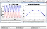
A commonly used test in production testing is the ADC static testing where INL, DNL, offset and gain are the test metrics for the ADC. Though simple in setup, the picture shows all elements provided and modeled by the tool architecture. This is a common case of a full test validation that can be done by including all peripheral hardware used in production testing. The architecture components comprise now:- Test description model: the settings for ADC static linearity test. Power up sequence and test mode control. Pin selection for ADC register access and data word capture. It also inlcudes the pre-defined post processing for INL and DNL metrics.
- Tester Platform model: the test stimuli (up/down ramp) generated by an AWG or PSU model. At the capture side, a digital sense instrument model is applied to capture the ADC words at specified word sample rate.
- Loadboard model: depending on complexity of loadboard this model contains generally a model for simple resistors, filters or possibly transmission lines. The cable interconnect between tester and loadboard uses the tool library physical models which includes bandwidth limited attenuation.
- IC/DUT model: this is a customer provided abstract model of the DUT which resides in the EDA database. Customers may also choose to run the simulation on the transistor level at the expense of higher simulation times.